Blynk Virtual Pin Example
Connect a capacitor with a capacitance between 100uF and 1000uF from power to ground to smooth out the power supply. It can be control both With the internet Blynk app or Without the internet manually by touch sensor switch.

Blynk Iot Lesson 3 Virtual Pins To Push Pull Data Youtube
STICK THE SYSTEM.

. Learn ESP32 coding online - Use Wokwi ESP32 simulator for your next project. For example if you want a single app button to switch multiple relays on or off. This is the receiver pin used for serial communication.
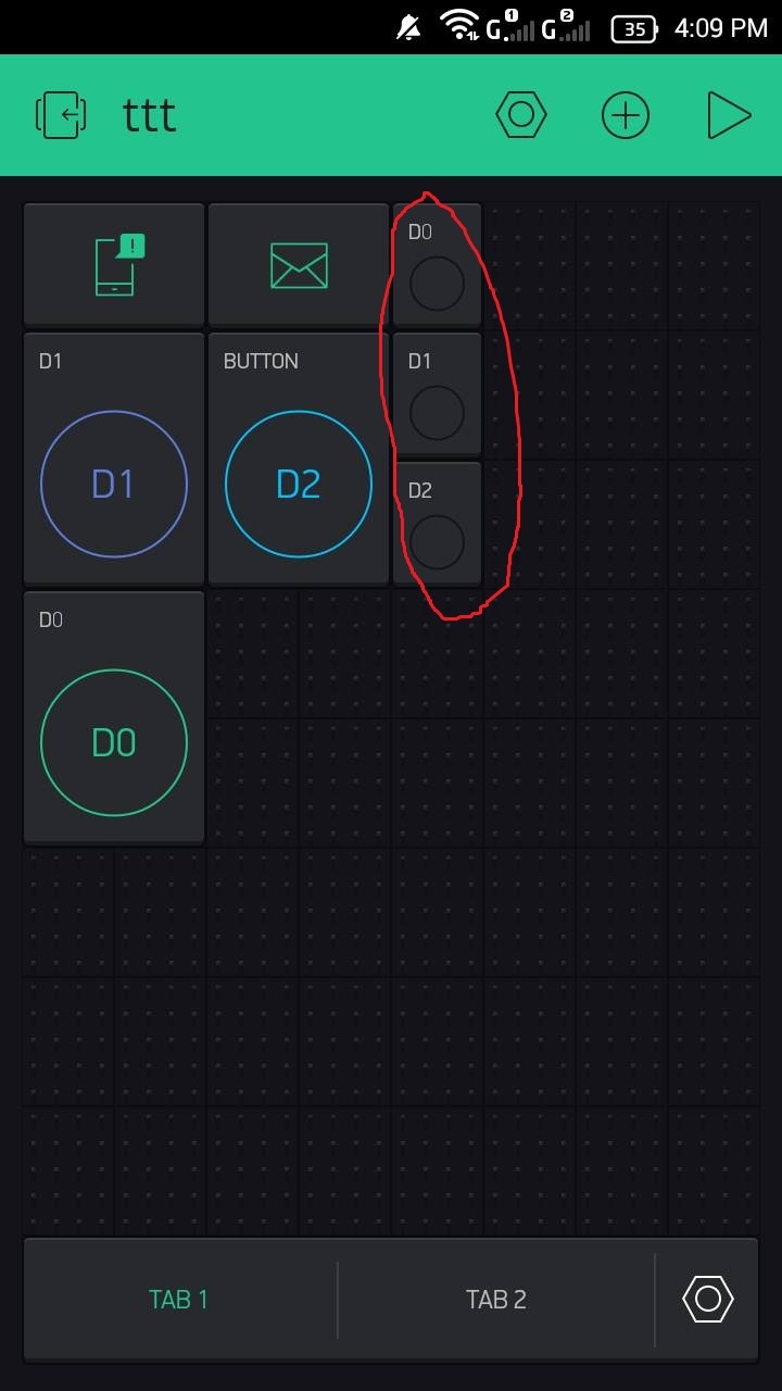
Use Blynk Example Code Builder Open Example Code Builder Choose your hardware model Choose connectivity type you use Add Auth Token it should be in your email Copy the whole code to buffer CTRLC 2. For example you can tell the button to set the GPIO on your device HIGH or LOW or you can send a specific value based on the state of the button. There opens Button Manager.
Assigning incoming value from pin V1 to a variable pwm pinValue. Blynk offers us several predefined components. So we would program the pin as 13 in the arduino code which we will shortly upload to the board.
Control 4 Relays using NodeMCU Real time feedback I have Modified the BlynkEdgentEdgent_ESP8266 example code httpsblynkio for this project Click on the following links to learn more. This is the transmission pin used for serial communication. Set to Integer data type connected to Virtual Pin 0 V0.
In this article we will look at how to use Python with serial ports so you can use it to interact with microcontrollers and other serial-port-enabled devices including those using virtual ports. And change settings in red. For any projects in the new Blynk IoT platform you will get all these files along with the.
This variable will be used to store the number which is sent from the Android cell phone. Click on New Datastream and select Virtual Pin. The main focus of the Blynk platform is to make it super-easy to develop the mobile phone application.
Email protected pgp bequ ga eamd bhe da ku fag db cbbc dhb ak bhe bi ddad nb bfge kb he aaaa aa fl dgbf haa uhuv nac nlg eh klca hhfa dad. Blynk works with hundreds of hardware models and connection types. As you will see in this course developing a mobile app that can talk to your Arduino is as easy as dragging a widget.
Now in the next window click on the sign to add a widget. I chose a slider and connected it to virtual 0 in the Blynk app. You can change slider label from hardware with.
It will be used in the Program. Control the speed with a software defined potentiometer with Blynk. Connect it with the 33V of the ESP32 board.
ESP32 simulator with Neopixel interface. Connect the TX and RX Pins of the Nodemcu ESP8266 wifi module with Pin number2 and Pin number3 of the Arduino. In this example the WS2812B LED strip will be powered using the 5V Arduino pin.
Connect a serial device to the port and verify its operation using commands or an application that supports the equipment. Short Pin 2 and 3 of the physical serial port. This is the ground pin that will be connected with the ground of the ESP32 board.
Enter a name select the virtual pin V1 and the datatype will be Integer. First of all open the Blynk application. Set slider value assigned to virtual pin V1 to 55.
After this Blynk will send an Authorization to the registered Email id. Blynk Application for the Water Quality Monitoring System. The display widget lcd is used to display the RFID code in a display widget in the Blynk App which is connected to virtual pin V1.
LED is connected with pin number 13 of the Arduino. Then I defined two variables password1 and password2 of the type long integer. This Pin will be accessed by the BLYNK App.
See the circuit In this example pin 13 connected to the internal LED pin 13 is blinking. Anything you connect to your hardware will be able to talk to Blynk. Select the Virtual Pin and Datatype from the dropdown menu as per the requirement.
Click on button you added. Click on the gauge enter the name as TEMP and select the virtual pin V2 select the reading rate as 1 Sec. For this purpose we integrate the library from Blynk.
Add Tip Ask Question Comment Download. Virtual Pins are a Blynk abstraction designed to exchange any data between your hardware and Blynk. Here I will control a relay so I have selected Integer For the Temparetute you have to select Double datatype and related UNIT.
To setup the Blynk interface you need to use three virtual. To do this I use 3 virtual Pin V1 V2 V3 and another Virtual Pin V4 for the Slider button to control fan speed in Blynk app. It also has switching status feedback system in.
Note down the Auth Token Code. For example turn on button assigned to virtual pin V1. Click on the gauge enter the name as EC and select the virtual pin V3 select the reading rate as 1 Sec.
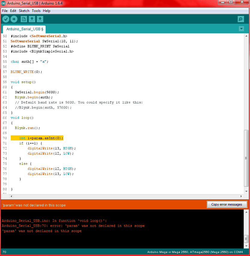
For example lets say street A is a busy street and we see that the garbage fills up really fast whereas maybe street B even after two days the bin isnt even half full. BLYNK_WRITEV0 int pinValue paramasInt. Inside the Widget box select the Map widget.
Add a LCD widget to the. You have far more control over what your widgets do when using Virtual Pins. You should get Auth Token in the Blynk App.
Thats it our Blynk app is ready. Now According to the Pin mapping diagram of Esp8266 board D7 pin is the 13th pin. In my case Im controlling 14 LEDs.
In output select Digital 13th pin. Pin 12 gets connected to the RESET pin by one wire-Typically this would be a problem because when the application starts up all pins get pulled LOW. Since we used Blynk the code architecture is used from Blynk example - Virtual Pin Read.
Click again on the screen and add another gauge. In the Arduino IDE load the ESP8266_Shield example via File Examples Blynk Boards_WiFi. You can also get button state from server in case your hardware was disconnected with Blynk Sync feature.
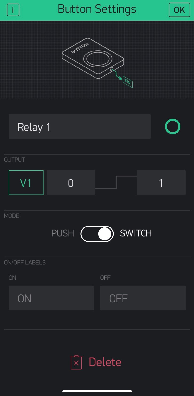
In BlynkConsole well leave the values set to 0 and 1 so the widget sends a 0 when its turned off and a 1 when its turned on. Electronically using only 1 wire connecting an OUTPUT pin 12 in this example to the RESET pin. Doing this will short the serial ports Rx and Tx pins.
If you want to control many LEDs youll need to use an external power source. On the third line I defined a variable data of the type long int. The result is that any data sent through the terminal will be echoed back to it.
Select ADD DEVICE and add Button. This is the VCC pin used to power up the GPS module. The pin number is the Rx while Pin number 3 is the Tx.
Then click on Create. The connection is pretty simple just connect the Led to D7 pin. Connect Ground Pin of the Nodemcu module with the Arduinos ground.
Blynk Example for ESP8266 and ESP32. After this click on the MAP widget and select virtual pin V0 as INPUT. There are 2 ways you can find the correct code for your hardware.
With Blynk you can create smartphone applications that allow you to easily interact with microcontrollers or even full computers such as the Raspberry Pi. Click on the PIN and select the PIN type as Virtual and the Pin name as V0. Echo of sensor goes to pin 13 of arduino.
Python is a useful language thanks to its simplicity functionality and platform-independent nature. If you do not have any potentiometers at your disposal you can also use software-based potentiometers. Connect the blue wire with the Arduinos Analog pin A0.

Using Virtual Pins Blynk Community

How Do I Use Virtual Pins As Buttons Hardware And Blynk Libraries Blynk Community

Using Virtual Pins To Control Physical Devices Faq Blynk Community

Comments
Post a Comment